| Kabalsrealm.com!! Who'dda thunk it!! |
|
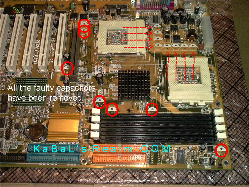
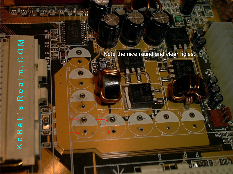
The removal is undoubtedly the most difficult and tedious part of this whole ordeal. Most all motherboards are comprised of a 6-layer PCB, with very tiny solder pads and holes. The problem that a 6-layer PCB presents is the fact that there is a very small tube through the entire thickness of the motherboard that the components' lead solders to insuring the component is making solid contact with the foil traces in necessary layer of the motherboard. This means that the entire hole is filled with solder, not just the visible surfaces. The solder needs to be removed without removing or damaging the tube or the foil around it. If the through hole tube or foil are damaged, it's instant death to your board! If you have soldered a motherboard before, you know what I am talking about!! Removing the actual component in itself is relatively simple. Clearing the hole of the remaining solder in order to install the new component is what can be a nightmare!! If you have the proper tools and a little ingenuity, you will be able to do this without damaging or destroying your motherboard. I highly recommend NOT using a mechanical solder sucker, such as a sold-a-pult. The recoil of these can cause the tips to impact the board and damage the traces and through holes! If you insist on using a solder sucker, a pneumatic is the only way to go!! However, those on a home budget typically don't have the funds for such a nice piece of equipment, so use the dental pick! This is where your stainless steel needle pick comes in really handy!!! A dentist's pick is IDEAL for this!! To remove the capacitors, follow these steps: 1) Preheat your soldering iron to roughly 450 degrees Celsius, and connect the grounding strap to the metal shroud around the keyboard or USB ports. 2) Choose your first target capacitor, and heat the POSITIVE lead up until the solder melts, if it won't melt, flow some fresh solder onto the joint. That will melt it. With the iron still on the POSITIVE lead, push the capacitor toward the NEGATIVE lead until the POSITIVE lead is free of the board, and remove the iron from the board. 3) Now do the same to the NEGATIVE lead, and the capacitor will be free from the board. Discard the bad capacitor in the trash. 4) Now to clean the holes out. Reheat the hole on the back side of the board, if necessary, melt a little fresh solder into the hole to reflow it. Then using your dental pick, gently push the pick through the hole to remove the melted solder and viola!! You will have a clean open hole, ready to place a NEW capacitor in!! Do this to ALL the marked capacitors, removing them ALL before starting the installation of the new ones.
Now that wasn't so hard, was it........ :) |
Kabal's Realm
Last Updated:
Tuesday May 08, 2018
Established December, 1997
Copyright© 1997-2018, Kabalsrealm.com